
How to Size a Retarder-Prover for Your Bakery’s Actual Schedule
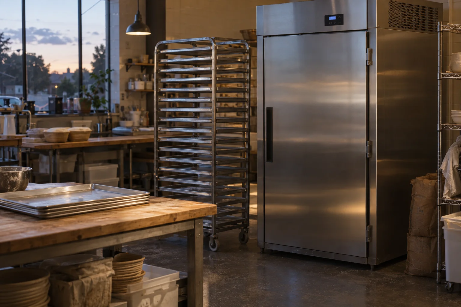
A bakery needing 28 trays can still outgrow a 36-position retarder-prover. If 21 trays need one programme and seven need another, two independently controlled 18-position chambers cannot take that split. Size the cabinet around the busiest overlap, then check that each programme has enough usable positions.
KW’s catalogue illustrates the problem. Our 7 October 2026 snapshot contains 17 prover listings, but only seven are marketed as retarder-provers. The remainder are proofing or proofing-and-holding products; their tray counts do not establish overnight refrigerated capacity. Even within those seven listings, tray format, position count and independent chamber capacity are different questions.
The buying brief needs three things together: a loaded tray drawing, a timed production schedule and the supplier’s confirmed loading arrangement. Begin with what the seven listings actually disclose.
What the seven retarder-prover listings actually tell you
We checked all 17 active prover-category entries in the catalogue database snapshot, kept the seven retarder-prover variants and recorded what their current pages state about loading. Where a page leaves a loading detail open, the table turns it into a question for the quote. These are catalogue listings, with stock availability to be confirmed separately.
| KW-listed configuration | Published loading information and the remaining question |
|---|---|
| BakerMax MPR-18 | Up to 18 layers of 400 × 600mm pans; trays excluded. Obtain the loaded-height allowance and accepted arrangement. |
| Everlasting RPE1790 | 20 levels at 48mm spacing or 18 at 72mm for 600 × 400mm trays. Choose the spacing for the loaded product, then use the corresponding count. |
| Everlasting RPE2790 | Page lists a 406 × 720mm tray kit and conversion to two 600 × 400mm trays per level. Adapter size and inclusion need reconciliation with the brochure. |
| Everlasting RPE5790S | Page lists a 406 × 720mm kit and conversion to two 600 × 400mm trays per level. Ask for the loaded count and the exact kit included in the quote, using the current spec sheet. |
| Everlasting RPE6600 | Modular room: 1–24 trolleys for 600 × 400mm trays. Panels arrive disassembled; a remote condensing unit is specified up to 15m away. Confirm the selected room configuration, trolley envelope and trays per trolley; ask how many loaded trays the proposed trolley arrangement will hold. |
| Turbo Air TDC-18-1R | Ask for tray format, spacing and capacity for each independently controlled programme; the inspected page leaves these open. |
| Turbo Air TDC-36-2R | Ask the same loading questions and confirm chamber controls. The “36” and “2R” model code alone is insufficient. |
The buying consequence: compare accepted loaded positions per compatible programme, not the largest number in a title. Two pages—TDC-18-1R and TDC-36-2R—leave even the nominal loading basis unresolved. RPE6600 states trolley capacity but does not establish how many loaded trays each trolley holds. A modular room also needs a different site and installation assessment from a cabinet.
The RPE2790 page describes a 406 × 720mm tray kit; the KW-hosted Everlasting brochure lists 406 × 730mm among optional rack adapters and excludes trays and containers. These may be different components, so the documents do not yet identify one agreed kit. Ask the supplier to name the quoted adapter, usable tray envelope and included parts.
Check the height of the loaded tray
Measure the tray’s outside dimensions and the tallest product at the relevant stage, including the tray and any covering or projection. Then ask for the supplier’s accepted support arrangement and airflow requirements for that load.
RPE1790 offers 20 levels at 48mm spacing or 18 at 72mm. Ask which arrangement suits the height of your loaded tray and leaves the required airflow.
Here is a geometric illustration, rather than a proposed RPE1790 configuration. Assume 20 equally spaced supports at 48mm and a tray plus product 90mm high. The next support is too close. Using alternate supports creates 96mm gaps and at most ten candidate positions. Only 6mm remains for support hardware and any necessary clearance; the supplier still needs to assess the real arrangement and the top position.
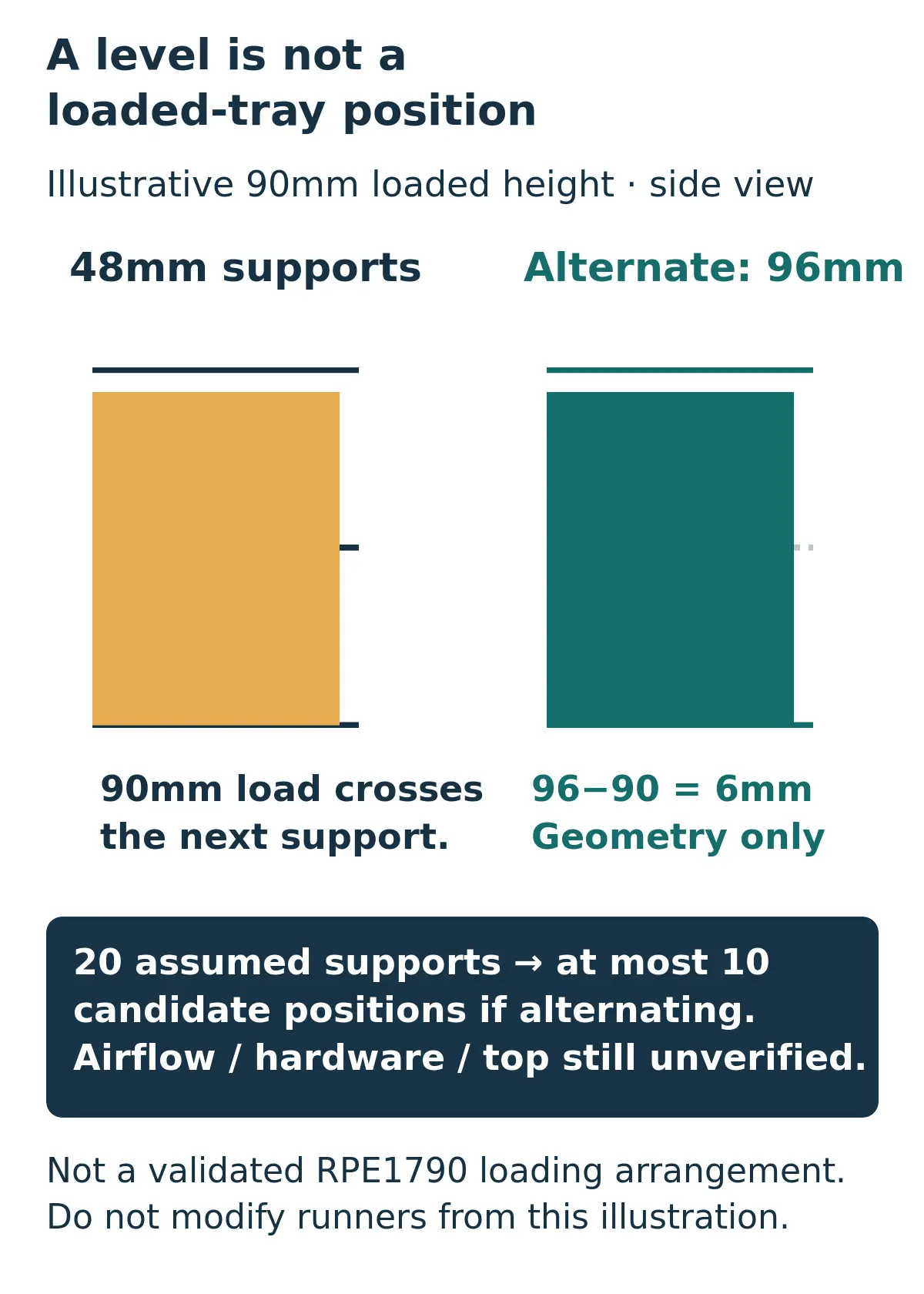
The purchasing consequence is straightforward: a 15-tray load fits under the headline count of 20, but exceeds the ten candidate positions in this sketch. Give the supplier your loaded tray drawing and ask for the actual usable count. Keep the real runners in their approved arrangement.
For a non-KW-listed reference example, Moffat’s Paramount RP1RS-2 lists 405 × 735mm or 457 × 735mm trays loaded long side first, two deep, on nine slides per chamber at 75mm gaps. Use it to see why rack format, tray orientation and the oven handoff must be matched together.
Count when space is occupied, including the oven queue
For each batch, record the tray count, cabinet-entry time, actual exit time and compatible programme group. Use dated times for work crossing midnight. Space becomes free when the batch leaves, not when the controller says its programme has finished.
Simultaneous load = trays already entered − trays already removed. Calculate it at every entry and exit event; the largest running total is the planning requirement for that programme group. If an entry and exit share a time, confirm that removal really precedes loading rather than quietly assuming the favourable order.
Use this hypothetical three-batch schedule to work out the overlap:
| Batch | Trays | Same-morning occupancy |
|---|---|---|
| A | 8 | 02:00–04:00 |
| B | 7 | 03:00–05:00 |
| C | 6 | 04:30–06:00 |
A and B overlap at 15 trays; B and C overlap at 13. The peak is 15, rather than the daily total of 21 or the largest batch of eight.
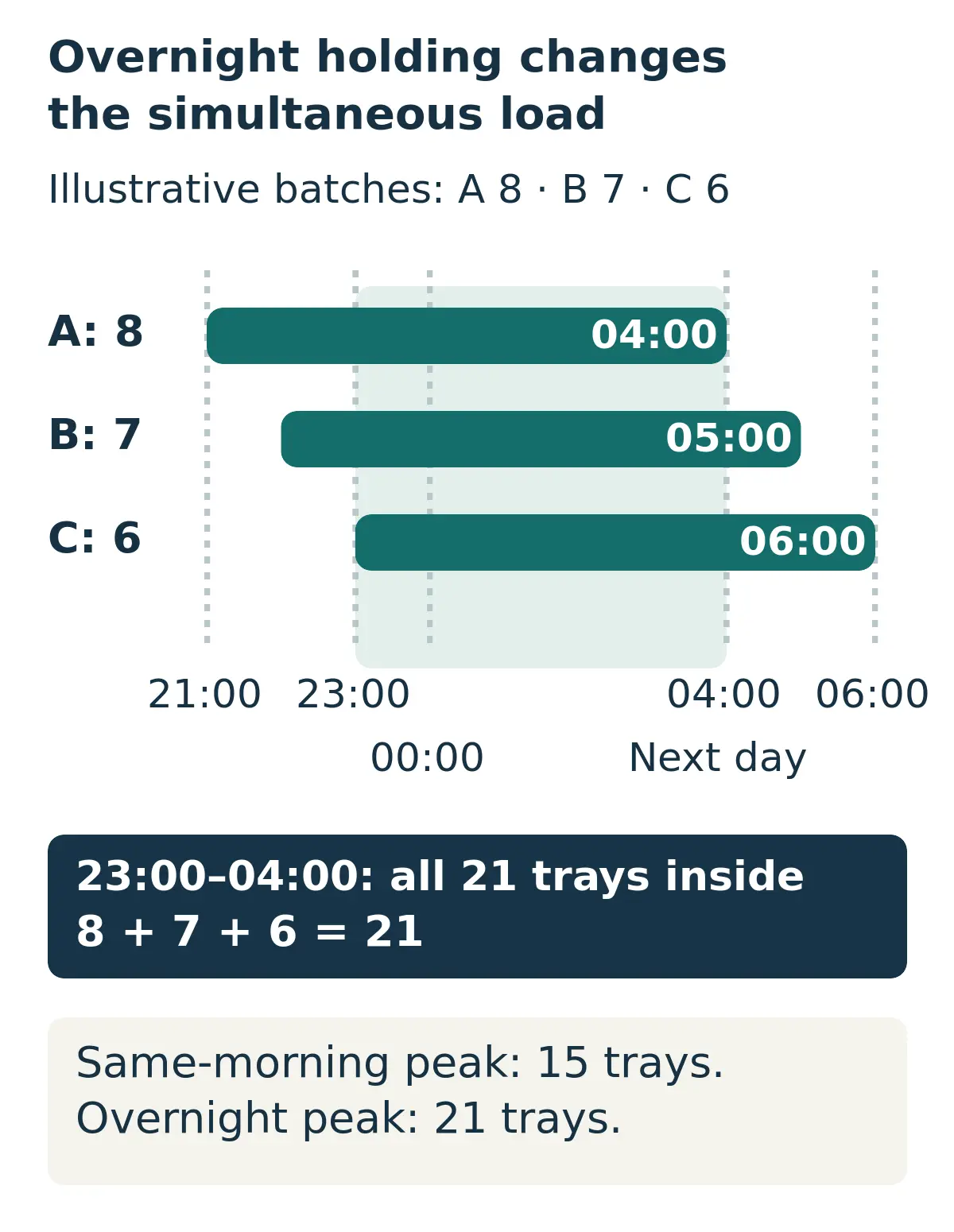
Change the process to overnight holding: A enters at 21:00, B at 22:00 and C at 23:00 on the previous date, retaining those morning exits. All 21 overlap overnight. The daily total is now the correct peak because every batch is present together.
Now delay A’s exit to 05:00 because the oven cannot receive it. The same-morning peak rises from 15 to 21; the overnight peak stays at 21. In both cases A’s dwell changes. Your process owner must decide whether that dwell is acceptable. If it is not, extra cabinet space does not repair the production schedule.
Allocate capacity to programmes, not doors
Make a separate occupancy calculation for batches that cannot share the required conditions. Then ask which chambers can run independently. Two doors do not establish two independent programmes.
Moffat’s RP1RS-2 lists two independent chambers with nominal 18-tray capacity each. Its page does not explicitly confirm separate programme control: obtain that confirmation before using them for incompatible batches. If independently controlled, consider a planning load of 21 trays in Programme A and seven in incompatible Programme B. The total, 28, is below 36, but the load cannot be allocated to two separate 18-position chambers: A exceeds either chamber, and using both for A leaves no independent chamber for B.
This hypothetical split exposes the question that a combined-capacity comparison misses: how many accepted positions can each independent programme actually use?
Test the operating schedule before adding positions
Ask three operating questions alongside the tray calculation:
- What enters the cycle? Record the dough’s entry condition and the intended retard/prove sequence. Ask the supplier and your process owner to confirm that sequence for the exact unit and batch; a cabinet marketed as a retarder does not establish how your incoming load should be conditioned.
- Who starts the next stage? Establish which transitions the quoted controller can schedule and which need a person present. Match those duties to the actual shift start rather than assuming every cabinet can finish proofing unattended.
- Who receives a delayed batch? Put the oven’s real receiving slots into the occupancy calculation. Agree who decides whether a delayed batch can remain under its programme, move to another accepted destination or needs a production change. An extra empty position cannot decide the dough’s condition.
These answers turn the 15-versus-21-tray calculation into a usable shift plan. If the operating sequence is unresolved, clarify it before increasing the order’s nominal capacity.
Check services and floor space before choosing the configuration
The inspected KW pages for RPE1790, RPE2790 and RPE5790S specify 240V / 15A and a 3/4-inch BSP water connection. RPE6600 instead lists 400V, disassembled room panels and a remote condensing unit up to 15m away. Put those different service requirements into the site brief alongside the tray count.
Put the exact-model installation documents in front of the responsible trades before ordering. Have them confirm phase, circuit and connection, water supply, any required filtration and drainage, operating clearances and access for installation and servicing. For the modular room, include the selected room size, panel assembly, condensing-unit location and connection route. Use the installation documents to resolve the remaining connection requirements.
Measure both the final footprint and the door/rack working area. Draw the route from unloading to that position; a cabinet or trolley that fits the floor plan can still fail at the doorway. Keep these site confirmations with the supplier's loaded-capacity answer so a larger capacity choice does not create an unresolved installation job.
Send a configuration brief the supplier can answer
Include your measured tray/rack drawing, loaded height, dated schedule and oven receiving times. Mark estimates and unresolved fermentation limits. Ask the quotation to return these answers together:
| Your input | Supplier confirmation needed |
|---|---|
| Loaded tray dimensions and orientation | Accepted arrangement and usable positions, not empty supports |
| Peak load for each programme | Capacity per independently controlled chamber; confirm control independence |
| Required adapters or rack | Exact parts, inclusions and any transfer to the oven |
| Supply and services | Exact voltage, phase, circuit/connection, water, drainage and any remote condensing unit; installation documents for the quoted unit |
| Site and route record | Final footprint, operating/service clearances, access and installation responsibility for the quoted configuration |
A written answer must bind the capacity to the proposed model and loading arrangement. If a field remains unknown, the capacity comparison is still incomplete.
Use the KW Prover range for the equipment handoff and KW’s enquiry form to send the schedule and drawings. If physical access is uncertain, supply the measurements in the delivery-route guide. Confirm that both the cabinet and its loaded rack can reach their working positions.
The useful answer is a supplier-confirmed configuration tied to your actual loads and programmes. A tray count without that binding remains an unanswered purchasing question.
Evidence: KW’s 17-listing category snapshot, with seven retarder-prover variants, checked 7 October 2026; the linked exact-model pages and documents. Counts describe listings, not market coverage or stock. Schedule and loaded-height examples are explicitly illustrative.